Wednesday, 27 May 2020

ASA Upgrade in Active and Standby Pair

Primary - copy running-config tftp: (Backup the configuratoin to TFTP Server)

Primary - copy tftp: disk0:  (Download the software and asdm image from TFTP Server)

Secondary - copy tftp: disk0: (Download software and asdm image the image from TFTP Server)

Primary - show bootvar; no boot system <old_image>; boot system <new_image>;

Secondary - show bootvar; no boot system <old_image>; boot system <new_image>;

  • Login to Primary ASA
    • check if it is active or not; (if active issue below command else – failover active- SSH Session of both Pri/Sec will be terminated)

failover reload-standby

After the standby firewall is UP

no failover active; SSH Session of both Pri/Sec will be terminated (Primary will become standby)

  • Login to Secondary ASA; (should be active now)
    • check if secondary is active or not;

failover reload-standby

  • Login to Primary ASA

failover active (should be standby)

Tuesday, 28 January 2020

HTTP/Path Redirection code/iRules in F5


when HTTP_REQUEST {
if { [string tolower [HTTP::host]] eq "hostname" and [HTTP::path] eq "/path" } {
HTTP::respond 301 Location "https://link"
}
}


when HTTP_REQUEST {
HTTP::redirect "https://link/"
}

Thursday, 21 November 2019

SPAN | RSPAN | ERSPAN

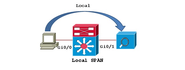
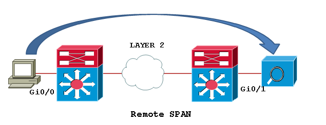
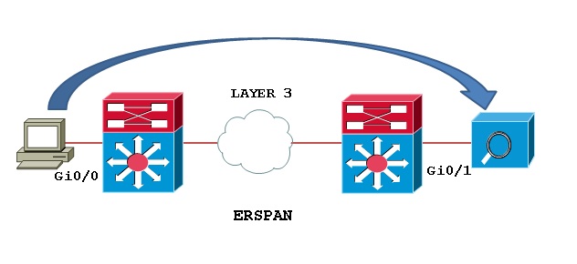
Switch port Analyzer (SPAN) is an efficient, high performance traffic monitoring system. It duplicated network traffic to one or more monitor interfaces as it transverse the switch. SPAN is used for troubleshooting connectivity issues and calculating network utilization and performance, among many others. There are three types of SPANs supported on Cisco products, which are illustrated in below diagram.

Types of SPAN:

Local SPAN: Mirrors traffic from one or more interface on the switch to one or more interfaces on the same switch.
SPAN1.jpg
Remote SPAN (RSPAN): An extension of SPAN called remote SPAN or RSPAN. RSPAN allows you to monitor traffic from source ports distributed over multiple switches, which means that you can centralize your network capture devices. RSPAN works by mirroring the traffic from the source ports of an RSPAN session onto a VLAN that is dedicated for the RSPAN session. This VLAN is then trunked to other switches, allowing the RSPAN session traffic to be transported across multiple switches. On the switch that contains the destination port for the session, traffic from the RSPAN session VLAN is simply mirrored out the destination port.
SPAN2.png
Encapsulated remote SPAN (ERSPAN): encapsulated Remote SPAN (ERSPAN), as the name says, brings generic routing encapsulation (GRE) for all captured traffic and allows it to be extended across Layer 3 domains.
SPAN3.jpg
ERSPAN is a Cisco proprietary feature and is available only to Catalyst 6500, 7600, Nexus, and ASR 1000 platforms to date. The ASR 1000 supports ERSPAN source (monitoring) only on Fast Ethernet, Gigabit Ethernet, and port-channel interfaces.

Thursday, 11 April 2019

DHCP with WLC

DHCP in WLC are of two types : Internal and External DHCP

Internal DHCP : DHCP server can be created in WLC.

Packet Flow
  1. Client send DHCP discover on all subnet as broadcast
  2. WLC forward the DHCP discover via DHCP proxy to internal DHCP server ip address(Management interface IP of WLC)
  3. Internal DHCP server send DHCP offer to WLC proxy agent.
  4. WLC send unicast DHCP offer to client with source address of WLC management Interface IP.
  5. Client send DHCP request to WLC on management interface IP.
  6. WLC send unicast DHCP request to internal server via DHCP proxy
  7. Internal DHCP server sends DHCP ACK to DHCP proxy.
  8. WLC send unicast DHCP ACK to client

External DHCP - (Proxy and Bridge)
  • Proxy – WLC becomes the proxy for DHCP messages.
Packet Flow
  1. Client boots up and send DHCP Discover on all subnet broadcast.
  2. WLC unicast this packet to DHCP server(as configured on WLC interface)
  3. DHCP server send DHCP offer to WLC.
  4. WLC unicast DHCP offer to Client with source address as WLC virtual IP address.
  5. Client send DHCP request to WLC on Virtual address because Client think that this virtual IP is DHCP server address
  6. WLC unicast DHCP request to DHCP server which returned the first offer to the client.
  7. DHCP server send ACK to WLC
  8. WLC unicast ACK from virtual IP to the client.
  • Bridging – DHCP messages are exchanged directly with client and DHCP Server.
Packet Flow
  1. Client send DHCP Discover on all subnet broadcast which is bridged by controller
  2. DHCP server send DHCP offer to Client
  3. Client send DHCP request to all subnet
  4. DHCP server send ACK to client in unicast packet

WLC - AP/Clients Supported

 
WLC Max AP Supported Max Client Supported
2504 75 1,000
3504 150 3,000
5500 500 7,000
5700 1,000 12,000
8540 6,000 64,000
WISM2 1,000 15,000
Flex 7500 6,000 64,000
Virtual WLC 200 6,000

Tuesday, 5 March 2019

Spanning Tree - Bridge Priority


Bridge ID consist of 8 Bytes and it is divided into two parts consisting of Bridge priority and Switch Mac Address.


To accommodate the additional VLAN information, Extended System ID field was introduced, borrowing 12 bits from the original Bridge Priority

Bridge Priority Field can only be set in increments of 4096.

This means that the possible values are : 4096, 8192, 12288, 16384, 20480, 24576, 28672, 32768 etc.

By default, Cisco’s Per-VLAN Spanning-Tree Plus (PVST+) adds this System ID Extension (sys-id-ext) to the Bridge Priority.

The two values (Bridge Priority + System ID Extension) together make up the Bridge ID which is used to elect the Root Bridge.

Monday, 25 February 2019

Understanding Access Point OS Images


All Cisco Aironet 802.11a/b/g/n and 11ac Wave 1 wireless access points and bridges currently being shipped run IOS, except for the OEAP602.

The newer 11ac Wave 2 APs, including the 1800, 2800 and 3800 series, run AP-COS.

Note: Some very old, no longer supported, Cisco access points ran VxWorks, such as the Aironet 342 and the 1010/1020 lightweight APs.

Access Point IOS is distributed as a tar file. These tar files can be downloaded from cisco.com SDS; lightweight IOS images (k9w8) are also bundled in the WLC software images (.aes.)


The AP image names include the following components:

platform-featureset-tar.version.tar

  • platform- the access point hardware model or family supported by the image
    • ap1g1- 700 series (702w beginning with 15.2(4)JB5)
    • ap1g2- 1600 series
    • ap1g3- 1530 series, AP803 embedded in IR829 router
    • ap1g4- 1850/1830/1810 series (COS not IOS)
    • ap1g5- 1800/1815/1540 series (COS not IOS)
    • ap3g1- 3500/1260 series
    • ap3g2- 3700/3600/2700/2600/1700 series (up through 8.4/15.3(3)JE branch)
    • ap3g3 - 3800/2800/1560 series (COS not IOS)
    • ap802 - AP embedded in 819, 812, 886VA-W/887VA-W, and C88x routers
    • ap801 - AP embedded in 861W, 891W, 1911W routers and most 88xW routers
    • apw5100 - Rockwell Stratix 5100 WAPAK9, WAPCK9, WAPEK9, WAPZK9
    • c3700- 1700/2700/3700 series APs (8.5/15.3(3)JF and above)
    • c1570- 1570 series outdoor APs
    • c1550 - 1550 (128MB model) series outdoor APs
    • c1520 - 1520 and 1550 (64MB model) series mesh APs
    • c1410- BR1410
    • c1310 - BR1310
    • c1250 - 1250 series APs
    • c1240 - 1240 series APs
    • c1200 - 1200 series (1200/1210/1220/1230)
    • c1140 - 1140 and 1040 series APs
    • c1130 - 1130 series APs
    • c1100 - 1100 series APs (i.e. the AP1121)
    • c520 - 521 AP
    • c350 - 350 series APs
  • featureset - the set of software features supported by the image - one of:      
    • k9w7 - autonomous (or "site survey") IOS (not available with COS)
    • k9w8- full lightweight IOS/COS (this is what is bundled in the WLC .aes image, and is factory installed on "mesh" APs)
    • rcvk9w8 - lightweight recovery image - this is factory installed on lightweight APs, unless a "mesh" image is specified; it lacks radio firmware (not available with COS)
    • boot- bootloader image (not IOS) - normally installed by manufacturing and not updated in the field
  • version - the IOS version       
Example:
c1240-k9w7-tar.124-25d.JA1.tar

  • Platform: c1240: 1240 series AP
  • Featureset: k9w7: autonomous IOS
  • Version: 124-25d.JA1: 12.4(25d)JA1
As AP IOS is always distributed as a tar file, the AP cannot directly execute such a file (thus, if you were to copy c1240-k9w7-tar.124-25d.JA1.tar directly onto AP flash, and then try to boot it, this could not work.)  The tar file contains, in addition to the IOS image proper, the radio firmware files, the HTML GUI files (if present), and various other files.

The AP IOS tar file must be bundled into AP flash using the archive exec command (this is done in an automated fashion when a lightweight AP is upgraded after joining a WLC.)

Example:
AP1260#archive download-sw /overwrite tftp://10.95.42.136/ap3g1-k9w7-tar.124-25d.JA1
After unbundling, the IOS image itself be in a file called flash:/platform-featureset-mx.version/platform-featureset-mx.version - for example,flash:/c1240-k9w7-mx.124-25d.JA1/c1240-k9w7-mx.124-25d.JA1.  The AP is configured to boot this image if the bootloader BOOT environmental variable is set accordingly.


To see what IOS image the AP is configured to boot, examine the BOOT variable.


Example:
AP3502i#more flash:/env_vars | include BOOT
BOOT=flash:/ap3g1-k9w8-mx.152-2.JA/ap3g1-k9w8-mx.152-2.JA

To change the BOOT variable, use the IOS config mode boot system command.

Example:
AP3502i (config) #boot system flash:/ap3g1-k9w8-mx.124-25e.JA2/ap3g1-k9w8-mx.124-25e.JA2

What are Sticky Clients ?

What are Sticky Clients ? CREDIT : http://wifinigel.blogspot.com/2015/03/what-are-sticky-clients.html One term you'll often hear banded ...