Monday, 25 February 2019

Understanding Access Point OS Images


All Cisco Aironet 802.11a/b/g/n and 11ac Wave 1 wireless access points and bridges currently being shipped run IOS, except for the OEAP602.

The newer 11ac Wave 2 APs, including the 1800, 2800 and 3800 series, run AP-COS.

Note: Some very old, no longer supported, Cisco access points ran VxWorks, such as the Aironet 342 and the 1010/1020 lightweight APs.

Access Point IOS is distributed as a tar file. These tar files can be downloaded from cisco.com SDS; lightweight IOS images (k9w8) are also bundled in the WLC software images (.aes.)


The AP image names include the following components:

platform-featureset-tar.version.tar

  • platform- the access point hardware model or family supported by the image
    • ap1g1- 700 series (702w beginning with 15.2(4)JB5)
    • ap1g2- 1600 series
    • ap1g3- 1530 series, AP803 embedded in IR829 router
    • ap1g4- 1850/1830/1810 series (COS not IOS)
    • ap1g5- 1800/1815/1540 series (COS not IOS)
    • ap3g1- 3500/1260 series
    • ap3g2- 3700/3600/2700/2600/1700 series (up through 8.4/15.3(3)JE branch)
    • ap3g3 - 3800/2800/1560 series (COS not IOS)
    • ap802 - AP embedded in 819, 812, 886VA-W/887VA-W, and C88x routers
    • ap801 - AP embedded in 861W, 891W, 1911W routers and most 88xW routers
    • apw5100 - Rockwell Stratix 5100 WAPAK9, WAPCK9, WAPEK9, WAPZK9
    • c3700- 1700/2700/3700 series APs (8.5/15.3(3)JF and above)
    • c1570- 1570 series outdoor APs
    • c1550 - 1550 (128MB model) series outdoor APs
    • c1520 - 1520 and 1550 (64MB model) series mesh APs
    • c1410- BR1410
    • c1310 - BR1310
    • c1250 - 1250 series APs
    • c1240 - 1240 series APs
    • c1200 - 1200 series (1200/1210/1220/1230)
    • c1140 - 1140 and 1040 series APs
    • c1130 - 1130 series APs
    • c1100 - 1100 series APs (i.e. the AP1121)
    • c520 - 521 AP
    • c350 - 350 series APs
  • featureset - the set of software features supported by the image - one of:      
    • k9w7 - autonomous (or "site survey") IOS (not available with COS)
    • k9w8- full lightweight IOS/COS (this is what is bundled in the WLC .aes image, and is factory installed on "mesh" APs)
    • rcvk9w8 - lightweight recovery image - this is factory installed on lightweight APs, unless a "mesh" image is specified; it lacks radio firmware (not available with COS)
    • boot- bootloader image (not IOS) - normally installed by manufacturing and not updated in the field
  • version - the IOS version       
Example:
c1240-k9w7-tar.124-25d.JA1.tar

  • Platform: c1240: 1240 series AP
  • Featureset: k9w7: autonomous IOS
  • Version: 124-25d.JA1: 12.4(25d)JA1
As AP IOS is always distributed as a tar file, the AP cannot directly execute such a file (thus, if you were to copy c1240-k9w7-tar.124-25d.JA1.tar directly onto AP flash, and then try to boot it, this could not work.)  The tar file contains, in addition to the IOS image proper, the radio firmware files, the HTML GUI files (if present), and various other files.

The AP IOS tar file must be bundled into AP flash using the archive exec command (this is done in an automated fashion when a lightweight AP is upgraded after joining a WLC.)

Example:
AP1260#archive download-sw /overwrite tftp://10.95.42.136/ap3g1-k9w7-tar.124-25d.JA1
After unbundling, the IOS image itself be in a file called flash:/platform-featureset-mx.version/platform-featureset-mx.version - for example,flash:/c1240-k9w7-mx.124-25d.JA1/c1240-k9w7-mx.124-25d.JA1.  The AP is configured to boot this image if the bootloader BOOT environmental variable is set accordingly.


To see what IOS image the AP is configured to boot, examine the BOOT variable.


Example:
AP3502i#more flash:/env_vars | include BOOT
BOOT=flash:/ap3g1-k9w8-mx.152-2.JA/ap3g1-k9w8-mx.152-2.JA

To change the BOOT variable, use the IOS config mode boot system command.

Example:
AP3502i (config) #boot system flash:/ap3g1-k9w8-mx.124-25e.JA2/ap3g1-k9w8-mx.124-25e.JA2

Monday, 18 February 2019

Configuration for NAT and PAT

Types
1. Dynamic NAT to a pool
2. Static NAT
3. PAT to a specific address(overload)
4. PAT to the outside router address (overload)

Configure the Access List
Router(config)#access-list 10 permit 10.0.0.0 0.255.255.255
Router(config)#access-list 20 permit 192.168.0.0 0.255.255.255
Router(config)#access-list 30 permit 30.0.0.0 0.255.255.255

Assign the Pool
Router(config)#ip nat pool POOL-10-4NAT 23.0.0.20 23.0.0.254 prefix-length 24
Router(config)#ip nat pool POOL-20-4PAT 23.0.0.11 23.0.0.11 prefix-length 24

Configure the NAT and PAT
Router(config)#ip nat inside source list 10 pool POOL-10-4NAT
Router(config)#ip nat inside source static 172.16.0.1 60.0.0.10
Router(config)#ip nat inside source list 20 pool POOL-20-4PAT
Router(config)#ip nat inside source list 30 interface [outside interface] overload

Router(config)#int [inside-interface]
Router(config-if)#ip nat inside

Router(config)#int [outside-interface]
Router(config-if)#ip nat outside

Friday, 15 February 2019

Configuring Bridge in Cisco AP

Add AP Mac Address in Security-MAC Filtering


Make sure that WLC is configured with single country code, Mesh AP will not join WLC if it has more than 1 country code configured.


Configure Both AP Mode to Bridge


When an AP Joins WLC go to AP and select RootAP - AP which will be connected to Wired end.


When an AP Joins WLC go to AP and select MeshAP - AP which will be creating backhaul connectivity using wireless and which does not have flexibility to connect Wired network.(could be turned on by Power Adapter or Power Injector)


Check the neighbor details by going at the end of AP, click on neighbor information tab.


Parent is configured as RootAP and the Child is configured as MeshAP

Parent

Child


That is all about basic configuration of Bridging.

Tuesday, 12 February 2019

AP Discovery Process

Below is the AP Discovery Process to find WLC.


Challenge for an AP is where to send CAPWAP Discovery messages so for that AP goes through hunting process to find WLC.

  • AP will send DHCP discovery request to get IP address unless it has previously configured static IP.
  • AP sends Layer 3 broadcast [255.255.255.255] to find WLC.
  • It looks for WLC information in option 43 inside DHCP offer to send the discovery request.
  • It will try to resolve CISCO-CAPWAP-CONTROLLER.local-domain or CISCO-LWAPP-CONTROLLER.local-domain to get the IP address of WLC.
  • Previously known WLC IP, AP remembers upto 24 previously learnt WLC IP Address.
  • Statically configured from WLC.
  • Statically configured from AP CLI.

Mobility Group / List / Domain RF Group


At the beginning of the world, wireless networks were small: one controller and a few access points. Then, the young Airespace company (some of you may even remember the even older name, Blackstorm Network) started having larger clients, needing several controllers. Some of them wanted to have controllers isolated from one another, some others wanted a "cluster logic" between controllers, to create a larger virtual controller.


So the Airespace team created the Mobility Group concept, also called Mobility Domain (these two terms mean exactly the same thing). If two controllers belong to the same mobility group, they exchange information about clients (namely, when a new client connects to a controller, this controller informs the other controllers. The result is that when the client roams to another controller, the new controller knows if it is a "new" client (no controller reported this client before), or a roaming client (one controller in the group/domain reported this client before). If it is a roaming client, you can even know which controller the client is coming from, which is very handy to transmit the client credentials from one controller to the other. You could have 12, then later on 24 controllers in the same mobility group/domain.

To make two controllers members of the same mobility group, you needed two steps:
1. Input the same string in the Controller > General > Mobility Domain Name field, so that both controllers have the same mobility group/domain value.
2. Inform each controller about the other, in Controller > Mobility Management > Mobility group. Each controller needs to know the other controller's Management IP address and built-in MAC address.

As a side effect of roaming, we also used to say that if you want roaming to occur smoothly, you'd better run the same code on both controllers (so that they speak the exact same language), and also configure the same virtual gateway IP address (this address is used as a "virtual address" to make the client think that it connects to one big virtual controller instead of several physical controllers).


At that time life was simple... :-) Then some clients also asked to segregate RRM... this was their scenario (kind of): I have 3 controllers, 2 in my office building and one in my warehouse. I want roaming between all of them (okay, so same mobility group/domain and controllers know each other) BUT I do not want cooperation for RRM between the office building and the warehouse. Why? Basically because the warehouse is a specific environment, most of the time isolated from the office and it has specific settings, so I do not want a sort of global master of the network that would not be able to distinguish the warehouse environment from the office environment.

Fine! We are going to create another group concept, the RF-Group (defined in Controller > General). You can put one string for the office building controllers, and another string for the warehouse controller. IF the strings are different, the controllers won't work together for RRM management...

Ok, this is how it works: when you add controllers to the local Mobility group/domain, those controllers send an introduction message to each other (hey, I am X, and oh BTW, my RF-Group is Y). All members of the mobility group also having a common RF-Group value elect an RF-Group leader. The RF-Group leader decides of an RF-Group hash (that represents this RF-Group name shared by those controllers) and sends it back to all members of the RF-Group.

Then, each AP sends, every 60 seconds, a RRM neighbor message from its radios, on all serviced channels. This message contains, among other things, the RF-Group hash. Neighboring APs hearing this message forward it to their respective controller. The controller looks carefully at the message and reads the RF-Group hash value. 2 possibilities:

1. The read RF-Group hash value is different from the RF-Group hash known by the local controller (so the other controller is part of another RF-Group, or the controller to which the AP is connected is unknown to the local controller RF-Group leader): the local controller despises and proudly drops the RRM neighbor message (this is from the RRM standpoint, your good controller may send alerts about rogues etc, but it does not see the neighbor as an RRM partner).

2. The read RF-Group hash value is the same as the RF-Group hash known by the local controller. In that case, the local controller thinks "hey, we are part of the same gang! We should work together on this RRM thing." The controller writes downs which of its access points hear which other controllers access points, and forwards this information to the RF-Group leader. Every 600 seconds by default, the RF-Group leader sends its instructions to the members of the RF-Group: you do this, you do that.


So you can clearly see here that the RF-Group is thought as a sub-group of the mobility group/domain. The other controller needs to be known to the local controller in order to be part of the same RF-Group and gets the same hash... and nothing in the RF-Group configuration allows you to tell the local controller about the other controllers, so it has to be done through the Mobility group/domain. So you configure Mobility group members, and among them some have the same RF-Group value and also share RRM information... limitation was 20 controllers part of the same RF-Group (so 24 controllers in the same mobility group, but yes, 20 members of the same RF-Group max).


Then some more complex scenarios (and more demanding clients?) appeared. They said: your stuff is cool, but does not work as it is, for 2 reasons:

- I want to roam across more than 24 controllers (I have a supabig network)
- I want APs in 2 mobility groups to exchange RRM information. For example, I have 2 floors, 1 controller per floor; people are not roaming from one floor to the other (coz they don't fly through ceilings), but the APs hear each other. So I don't want controllers to exchange information about clients (because it wastes bandwidth as these people will never roam from one controller to the other), but I do want them to exchange RRM information, so that they do not stupidly stay on the same channel.


Okay, it was time to extend the system... and the mobility group/domain concept became the mobility list... the idea is that your controller can know guys with the same Mobility group/domain value, and other guys with another Mobility group/domain value. Your list can contain up to 48 names in controller code 5.0, and 72 on 5.1 and later (so in the CCIE exam, we are still for now on code 4.2, with one mobility group of 24 members max). The key concept is that you do not need to have the same mobility group value to roam. As long as controllers know each other (they are on each other mobility list), they exchange information about connecting clients. The mobility list is what where we used to configure mobility group members before, defined in Controller > Mobility Management > Mobility groups (notice the plural form now).


So what is the difference? Do we still need to care about the Mobility group/domain value? Well, yes! There is a huge difference between mobility group (guys having the same mobility group/domain name as yours) and mobility list (other controllers you know, but that have a different mobility group/domain name from yours): CCKM (Cisco Centralized Key Management) and PKC (proactive Key Caching) do NOT work across mobility groups. This means that if you roam to a controller you know but that has another mobility group value, everything is fine is you use pre-shared key (or open or Web authentication). If you use 802.1X with CCKM or WPA2, your key will not get transmitted to the other controller... and the practical result is that you will have to re-authenticate to get a new key. You will keep your IP address though (as part of the roaming process), so the effect is that you will be briefly disconnected, but your IP session will not be broken. So this is fine if you are a data device. If you are a VoWLAN device, you do not want this disconnection, and you will make sure that controllers you roam to belong to the same mobility group.

So there is still roaming across mobility groups: when you get to new controller, it recognizes you as a valid client coming from another controller, and accepts you. It just fails getting your key if your use CCKM or PKC.


The RF-Group remains unchanged: all members of the same mobility list exchange introduction messages. Those that share the same RF-Group value elect a group leader and start working together on RRM... simple, isn't it?

Monday, 11 February 2019

Hotspot 2.0

Making the Wi-Fi Roaming Experience as Secure and Easy to Use as With Cellular Hotspot 2.0 is focused on enabling a mobile device to automatically discover APs that have a roaming arrangement with the user’s home network and then securely connect. This is very much the cellular experience that we all enjoy when getting off an airplane just about anywhere in the world. Wi-Fi roaming would apply anytime a mobile device does not see an AP belonging to its home network provider. A user could roam on a Wi-Fi network that is across town or on the other side of the world. Roaming partners can include MSOs, MNOs, wireline operators, public venues, enterprises, and basically any other entity that has Wi-Fi assets. Roaming can be accomplished with dual mode devices (smartphones) or Wi-Fi-only devices like tablets and laptops.

With Hotspot 2.0, the client device is equipped by an authentication provider with one or more credentials, such as a SIM card, username/password pair, or X.509 certificate. The device can then query Hotspot 2.0 capable APs to see if it belongs to a visited network that supports roaming with the devices home network.

Hotspot 2.0 is a program of the Wi-Fi Alliance, and is supported by the Passpoint(™) certification program which ensures APs and client devices comply with the technical specifications. Hotspot 2.0 capabilities are emerging in a series of releases. Release 1 came out in June 2012 and was focused on automating network discovery/selection, authentication, and over-the-air security. Other releases will follow in the coming years that will add additional capabilities. Mobile devices with Hotspot 2.0 support are now available in the market. While vendors may choose to introduce new models to enable Hotspot 2.0, these capabilities can be added via software updates in most cases.

To enable a compelling roaming experience, groups such as the Wireless Broadband Alliance and CableLabs are working to create frameworks and standards for the linking of various operators’ authentication domains. And a number of companies are interested in providing “roaming hubs’ that would provide an authentication service for Wi-Fi network providers.

The hassles and risks of connecting to public Wi-Fi will soon be a thing of the past, thanks to Hotspot 2.0.
Hotspot 2.0 Release 1
Release 1 is focused squarely on over-the-air security and network discovery and selection. The key enabling protocols are IEEE 802.11u, along with IEEE 802.1X, selected EAP methods, and IEEE 802.11i. The latter three are part of the WPA2- Enterprise certification program in the Wi-Fi Alliance, and are standard on all smartphones. While the certification is called "WPA2-Enterprise", the end result is a process that is every bit as secure and easy to use as what exists in the cellular world.
The IEEE 802.11u protocol enables a mobile device to have a dialog with a Wi-Fi AP "pre-association" to determine the capabilities that the network can support. The two protocols that 802.11u uses to make this happen are the generic advertisement service (GAS) and the access network query protocol (ANQP). These protocols run on top of 802.11 and enable the Hotspot 2.0 experience

Hotspot 2.0 protocol stack

 Hotspot 2.0 protocol stack

The Process of Network Discovery and Selection

When a user with an HS2.0 capable mobile device comes within range of a Hotspot 2.0 capable AP, it will automatically open up a dialog with that AP to determine its capabilities. This is done using ANQP packets that are carried at layer 2 by the GAS service (Note: the device has not yet attached and does not yet have an IP address). It is the exchange of ANQP packets that allows the mobile device to automatically learn the capabilities of an AP. A few of the more important capabilities include:

1) The domain name of the network operator. If the AP is part of the user's home network then no roaming is required and the user can move straight to authentication. If the AP is not on the user's home network, then roaming is required.
2) If roaming is required, then the list of roaming partners that are supported by that AP must be passed down to the mobile device via the ANQP protocol. This can be provided in the form of a PLMN (Public Land Mobile Network) ID, realm, or the organizational identifier (OI):
  • 3GPP PLMN ID (MCC plus MNC) would be the preferred method for a mobile operator. MCC refers to the mobile country code and MNC to the mobile network code.
  • NAI Realm List (username@domain name) would be the preferred method to identify most non-mobile operators like MSOs, wireline operators, and public venues.
  • IEEE Organization Identifier (6 hexadecimal digits that many would recognize as the first 3 bytes of a MAC address). The WFA recommends that national and international SPs have an Organization Identifier (OI). The two primary use cases for OI are as follows:
    • A small number of OIs can be put in the AP's beacon; if the mobile device recognizes the OI, it doesn't need to use ANQP to determine if it can successfully authenticate at that AP. This can conserve the mobile's battery as well as reduce the time to associate.
    • Some SPs may wish to sell subscription levels (e.g., gold, silver, bronze) in which not all subscribers have access at every AP. For example, gold users might have access privileges at all APs in an operator's network, but bronze users might not be authorized to use an operator's APs in premium locations.
It is possible that service providers might advertise roaming consortiums in more than one way. A mobile operator might advertise both a PLMN ID and a realm. The former is used for SIM-based devices and the latter for non-SIM devices. A wireline operator or an MSO would only advertise their realm, as they don't have a PLMN ID.

3) Other attributes that can be relayed to the mobile device include backhaul bandwidth and loading on the access network. This is useful information if there is more than one AP that can roam with the user's home network. Other details that are passed down to the phone as part of the HS2.0 process include:

  • The operator friendly name (San Jose Airport for instance). This can be displayed on the mobile device once the connection is established and is fairly standard when roaming on cellular networks.
  • Venue type (stadium or hospital)
  • IP Address Type (v4/v6)
  • Internet access or walled garden
  • And more
Once the mobile device learns the roaming partners and the identity of the AP operator, it invokes some basic, built-in network selection policies to determine which AP to join. The basic policy provided by Passpoint Release 1 capable mobile devices is, in the absence of [overriding] user-configured preferences, to prefer Hotspot 2.0 compliant APs over legacy APs (i.e., non-Hotspot 2.0 APs) and to prefer an AP operated by the user's home operator over one operated by a visited operator. Users are allowed to specify that certain Wi-Fi networks should always have priority and these would typically include the user's home network and their work network.

The ability of the mobile device to "learn" about Wi-Fi network capabilities pre-association will completely transform the Wi-Fi user experience. It will also completely change the nature of an SSID (Service Set IDentifier). In the past, users and devices had to "remember" SSIDs that have provided connectivity in the past, so that they can be accessed again in the future. These are typically SSIDs for which they have credentials or which provide open access. With HS2.0 the importance of SSIDs will be reduced, and what really matters is does the visited AP have a roaming arrangement with my home network provider. In fact the notion of having an AP advertise many different SSIDs for different purposes will also be greatly reduced in favor of Hotspot 2.0 based advertisements. This should also enhance the performance of mobile networks, as it reduces the airlink traffic associated with the beacons generated by these additional SSIDs.

Secure Authentication

Hotspot 2.0 also requires the use of 801.1X authentication. Captive portal based authentication is not supported in HS2.0.1 As part of the 802.1X authentication process, the following EAP methods must be supported:

  • If a mobile device has a Subscriber Identity Module (SIM), then EAP-SIM as defined in RFC-4186
  • If a mobile device has a UMTS Subscriber Identity Module (USIM), then EAP-Authentication and Key Agreement (AKA) as defined in RFC-4187.
  • All mobile devices must support EAP-Transport Layer Security (TLS) as defined in RFC-5216 and which uses an X.509 digital certificate
  • All mobile devices must support EAP-Tunneled Transport Layer Security (TTLS) as defined in RFC-5281) along with MS-CHAPv2 which uses username and password, with a server side certificate
Credentials and EAP Methods in Hotspot 2.0

WPA2-Enterprise also requires that the airlink be encrypted using 802.11i. This addresses a security vulnerability with open access or portal based hotspots that don't provide airlink encryption. Hotspot 2.0 plugs this vulnerability with 802.11i, which uses AES (advanced encryption standard) technology. This combination of protocols is what enables Wi-Fi to be every bit as secure and easy to use as a cellular service. In addition, Hotspot 2.0 Release 1 improves upon WPA2-Enterprise security by eliminating the so-called "Hole-196" attack. In these attacks, a device can forge broadcast or multicast frames (as if coming from a legitimate AP) to initiate its attack.

Figure 2: Authenticating a roaming user to their home network

Figure 2: Authenticating a roaming user to their home network

Figure 2 shows the process by which a user in a visited network can have their authentication request proxied back to the home network. In this example the visited network could be an MNO, MSO, a private enterprise, a public venue (such as a hotel, convention center, airport, etc.), or wireline provider. Wi-Fi greatly expands the universe of possible roaming partners, and thus the utility of a Wi-Fi network.

Settlements and the Business of Roaming

Hotspot 2.0 will greatly enhance the opportunities for Wi-Fi operators to monetize their networks through roaming arrangements with other providers. These providers can include MNOs, MSOs, wireline providers, and a wide variety of enterprises including hotels, convention centers, hospitals, airports, etc. This also queues up the very important subject of settlements, which are used to make sure all operators (mobile or wireline) get paid for services rendered, if appropriate. In 2012, WBA updated their WRIX service specifications, which governs settlements and billing. Key elements include WRIZ-i (interconnect), WRIX-d (data clearing), and WRIX-f (financial settlements). These services can be deployed by the home and visited network providers, either directly of through a 3rd party WRIX service provider.

The Impact of Hotspot 2.0

Hotspot 2.0's impact on the industry will be enormous. Mobile operators are already seeing their networks overloaded by data traffic and are looking at all available options to increase densification. At the top of their list are technologies like Wi-Fi and LTE small cells. Cable and wireline operators are taking advantage of their backhaul capabilities to rapidly build-out an extensive Wi-Fi footprint. This technology has also been extensively deployed in public venues like hotels, airports, convention centers, stadiums, hospitals, etc. With Hotspot 2.0, it will now be possible to link together this huge footprint of Wi-Fi APs through a web of roaming arrangements. Users will be able to seamlessly roam onto Wi-Fi networks from almost any location.

The net result for the MNO is much greater network densification then could be achieved by building out a network of APs on their own and a much better experience for the subscriber. Users no longer need to know or care about SSIDs and authentication protocols. Instead, they get an always bestconnected experience.

Venue owners and operators can begin to better monetize their Wi-Fi network investments through these roaming arrangements and the settlements that they entail. A mobile operator that deploys a Wi-Fi network in a stadium can now monetize that asset by allowing subscribers of other operators to roam onto that network. Hotels can likewise allow subscribers of all the different mobile operators to roam onto their in-building Wi-Fi networks.

Hotspot 2.0 technology will radically transform the wireless industry, and it is set to emerge in 2013 in a very big way.

Credit : RuckusWorks


AP Authorization against an AAA Server

We will configure WLCs to use RADIUS servers to authorize APs. The WLC uses a LAP's MAC address as both the username and password when sending the information to a RADIUS server.

For example, if the MAC address of the AP is aa:bb:cc:dd:ee:ff, both the username and password used by the controller to authorize the AP is aa:bb:cc:dd:ee:ff.

Note: If you use the MAC address as the username and password for AP authentication on a RADIUS AAA server, do not use the same AAA server for client authentication. The reason for this is if hackers find out the AP MAC address, then they can use that MAC as the username and password credentials to get onto the network.
  
WLC Configuration
Go to WLC GUI, click Security AP Policies.
The AP Policies page appears.
Under Policy Configuration, check the box for Authorize MIC APs against auth-list or AAA.
When this parameter is selected, the WLC checks the local MAC database first. For this reason, make sure the Local database is empty by clearing the MAC addresses under the AP Authorization List. If the LAP MAC address is not present, it then checks the RADIUS server.
Click Security and RADIUS Authentication from the controller GUI to display the RADIUS Authentication Servers page. Then, click New in order to define a RADIUS server.
Define the RADIUS server parameters on the RADIUS Authentication Servers > New page. These parameters include the RADIUS Server IP Address, Shared Secret, Port Number, and Server Status.

ACS Configuration
Click Network Configuration > Add AAA Client.
The Add AAA Client page appears.
On this page, define the WLC system name, Management Interface IP address, Shared Secret
Click Submit + Apply.
Add the LAP MAC Addresses to the User Database on the Cisco Secure ACS.

Complete these steps in order to add the LAP MAC addresses to the Cisco Secure ACS:

Choose User and Identity Stores from the ACS GUI, create new user.
The username should be the MAC address of the LAP that you want to authorize.
The password should also be the LAP's MAC address.
Repeat this procedure to add more LAPs to the Cisco Secure ACS database.

Port based Authentication for Access Point

Access Point Configuration
capwap ap dot1x username <username> password <password>
By doing so capwap knows its dot1x credentials for authentication. Only after successful authentication capwap will initiate the discovery and joining process meaning that if there is an AP and it does not know the dot1x credentials, then it is not possible for that AP to send any capwap messages which results in preventing AP to join WLC.

Switch Configuration
Interface Configuration
switchport access vlan <vlan>
switchport mode access
authentication port-control auto
dot1x pae authenticator
spanning-tree portfast
Globlal Configuration
dot1x system−auth−control
aaa new−model
aaa authentication dot1x default group radius
radius-server host <IP Address> key <Password>

WLC Configuration
Here you need to provide 802.1x supplicant credentials for an AP to get the credentials to do the authentication.

All AP which is available in WLC will get to know the dot1x credentials so that if we configure the port as dot1x authenticator, AP would not have any issues in doing authentication.

The configuration here is globally and is applied to all the AP.
We can over-ride the above global configuration by assigning credentials in AP itself.
Once we add the credentials either globally or directly, it will be pushed immediately inside AP.

When we apply the commands in switchport, AP needs to now do the authentication then only it will rejoin back to WLC, meaning that AP will lose the capwap connectivity with WLC. And will rejoin the WLC.

ISE Configuration
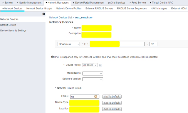
Adding Switch

Enable Radius (Define Shared Secret)

Create dot1x credentials (username and password) in ISE

Create Identity Group and define the credentials created in previous step


Create Policy Set


Keep Default Policy and use All_User_ID_Stores

Create Authorization Policy to permit access if the condition is matched

Thursday, 7 February 2019

10 Steps to Reset Cisco Catalyst Switch Password


Step 1: Connect your PC or terminal into the switch console port with the blue console cable.


Step 2: Open Putty or any terminal to console into the switch.


Step 3: Unplug the power cable to the switch.

Step 4: Press and hold the MODE button on the front of the switch and plug the power cable back into the switch (make sure while plugging in power cable mode button is pressed) After the power cable has been plugged in, wait a couple of seconds and then release the MODE button.

Step 5: Your display on Putty should look like this (switch:)

Step 6: Enter these commands into the switch
  • switch: flash _init
  • switch: load_helper
  • switch: dir flash:
[Check the flash and look for config file, if the name is config.text then change it.]
  • switch: rename flash:config.text flash:config.text.old
  • switch: boot
Step 7: Once the switch reboots, answer NO to “Would you like to enter system configuration dialog? [Yes/No]:

Step 8: Get into the privilege prompt.
  • Switch>enable
  • Switch#rename flash:config.text.old flash:config.text
  • Switch#copy flash:config.text system:running-config
  • Source filename [config.text]?
  • Destination filename [running-config]?
  • Press Enter to copy

Step 9: Get into global configuration
  • Switch#conf t
  • Switch (config)#enable secret password
  • Enter the password you would like

Step 10: Return to Privilege mode and save your config
  • Switch (config)#exit
  • Switch#copy run start

What are Sticky Clients ?

What are Sticky Clients ? CREDIT : http://wifinigel.blogspot.com/2015/03/what-are-sticky-clients.html One term you'll often hear banded ...